Cost, accuracy, repeatability and time.
Any CATIA® task that needs to be manually inputed or repeated, risks data entry errors or design sequence errors.
VB.net allows you to read in external data (text, csv, xml), ask for user input through a GUI, and then process it according to math and rules, over and over, leaving the creative tasks for the designer!
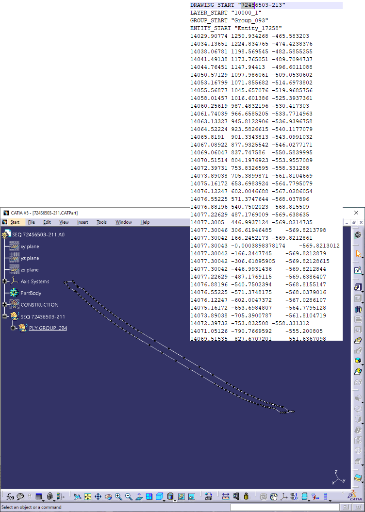
In this example we have over 11.000 lines of text and coordinates of output for a laser projector. The projected data will guide the mechanic laying a prepreg ply on a mandrel. Using VB.Vet we read in all the points, created lines between then, colored them red, green, blue and yellow to signify their orientation and presented it in a single CATPart for QA analysis
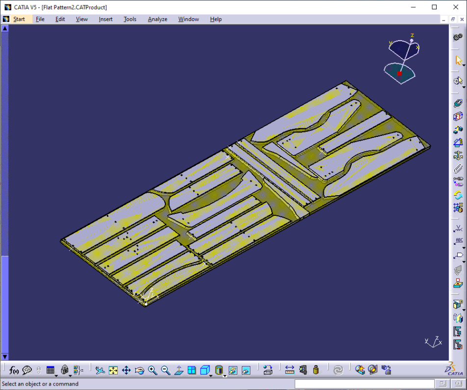
Previously a client was using CATIA® to create a CATProduct containing a 4x8 honeycomb sheet. They would then manually insert each detail part of the asset (of similar type and thickness) into the product, and manually constraining them to be 2" apart, then manually add tabb for each part. They would then manually NC Program the entire assembly.
This method was fine when the furniture was standardized. However they could not keep up with the NC workload once the company switched to custom interiors.
The solution was to create an NC library of all parts, write a series of VB.net programs to control all manufacturing data from start to finish, and generate automatic assembly diagram to show insert type and locations. Data flow was:
1. Read in Asset in CATIA® V5 and auto determine what parts are not in the current library.
2. Parts not in Library are put in an NC queue
3. NC has a program to translate part to local system and auto create Associated CATProcess. CATProduct with Engineering, Stock, tabs and a not to exceed frame. All components for Vericut are auto created.
4. Fnished programmed Parts are put on an NC Check Queue
5. Once checked, parts are added to the master library.
6. As needed, Individual parts are then automatically nested. Vericut data for the New assembly is then created for a final AutoDiff and collision check. Min Z values are verified for no table crashes. Gcode is then sent to the shop
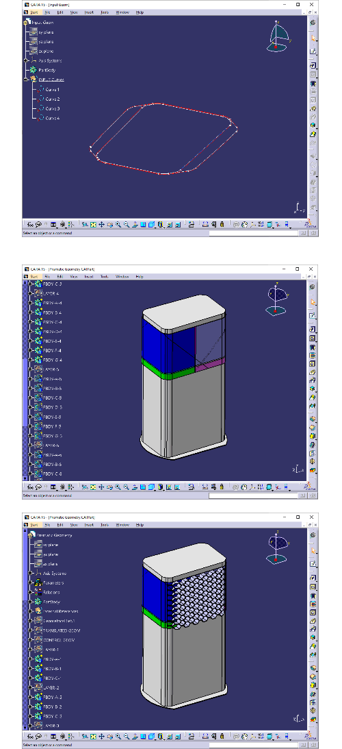
In this example we ask the user to select 4 input curves in CATIA® as seen in the top picture. We then automatically
1. Translate the curves from the Aircraft system to the Tooling system.
2. Create the Mandrel (white solid) in the mid picture
3. Create 4 solid boundaries for the 0, 90,45 and -45 tows for the inner skin (mid picture)
4. Create the Honeycomb geometry between the inner and outer skins with a user definable cell width (bottom picture)
5. Create 4 solid boundaries for the 0, 90,45 and -45 tows for the outer skin.
6. Create all drive curves for the tows
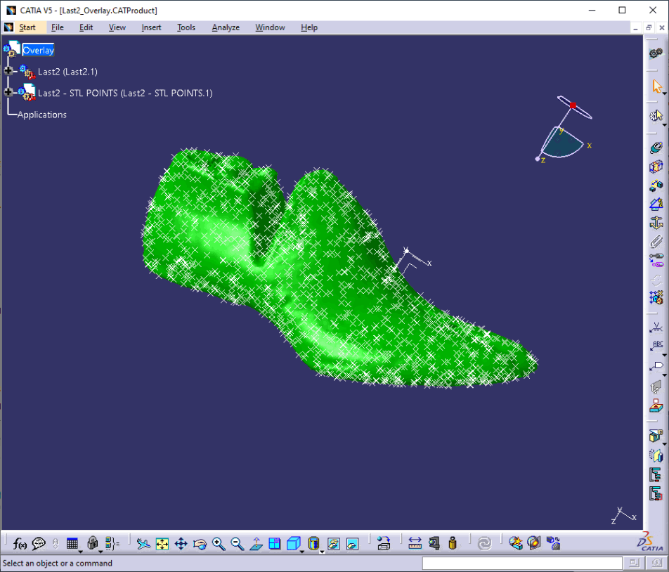
In this example we used a 3dsystems.com Sense Scanner to scan a Shoe Last. Using VB.net we converted the obj file to CATIA® points and auto created the CATProduct containing a Part Instance or the reference Last and a Part Instance of the Points.
Now the designer is free for the creative/feedback part to use the points to create the surfaces needed for manufacturing. The Last is hidden for the initial surface creation, then unhidden for a comparison, surfaces are then modified in a Newton Raphson loop.
Do you have any repetitious manufacturing, design or programming process that you would like to speed up/optimize? Give us a call.